It is a common security practice to setup a wireless guest network on a separate VLAN. This allows for complete isolation of traffic between your private and guest networks. This guide will only be covering how to implement this particular setup on MikroTik routers with built-in WiFi, such as the RB951, RB962, etc. Before going forward, I’m assuming that a private wireless network already exists and is fully functional. In addition, all screenshots and instructions in this guide are done using MikroTik’s WinBox software.
Create the Security Profile and Virtual AP
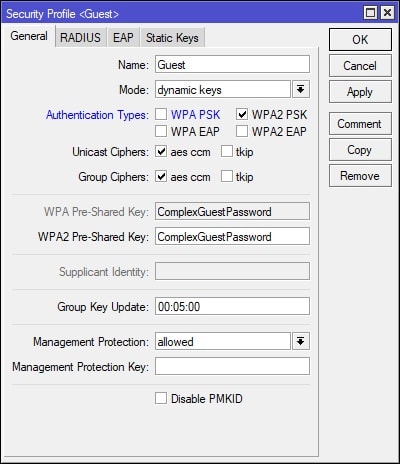
In Winbox, select Wireless on the left-hand side and navigate to the Security Profiles tab. Click the + (plus) button to create a new Security Profile. I’ve disabled WPA PSK, leaving only WPA2 PSK enabled. Also, ensure that you’ve set a secure/complex password. See screenshot for details:
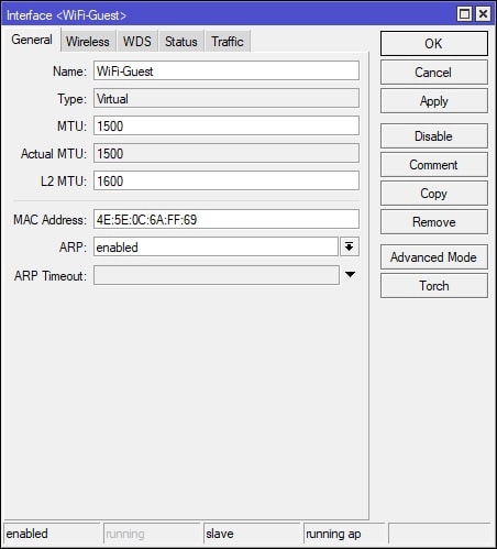
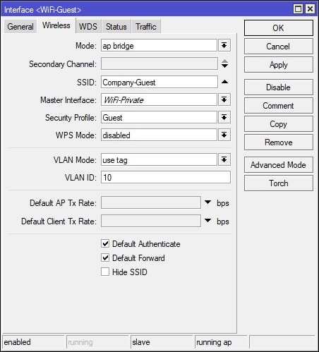
Afterwards, navigate to the WiFi Interfaces tab and click the + (plus) button and select “Virtual” from the menu. Under the General tab, set the Name for the Virtual AP, something descriptive, such as WiFi-Guest. Afterwards, navigate to the Wireless tab and set the SSID, Security Profile, VLAN Mode, and VLAN ID. The VLAN ID will match the VLAN interface that we will be creating in the next step. See screenshots for further details:
Create the VLAN Interface
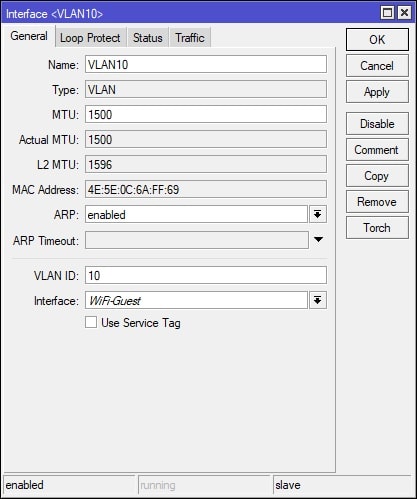
In Winbox, select Interfaces on the left-hand side and navigate to the VLAN tab. Click the + (plus) button to create a new VLAN interface. The VLAN ID is “10” and the Interface is “WiFi-Guest”, which are values that were set in the previous step, when creating the Virtual AP. See screenshot for details:
NOTE: The MikroTik may be using “Interface Lists” (Winbox: Interface > Interface List tab) in some of the firewall filter rules. If this is the case, you will want to either not use Interface Lists and use just interfaces, or make sure to add the new VLAN interface for the guest network to the existing LAN Interface List. If the MikroTik is using Interface Lists and you do not add the VLAN inteface for the guest network to the existing LAN interface list, then guests will be able to connect to the network, but will have no internet access. To be specific, the default MikroTik rule that requires the VLAN for the guest network to be added to the LAN Interface List is the following:
NOTE: The MikroTik may be using “Interface Lists” (Winbox: Interface > Interface List tab) in some of the firewall filter rules. If this is the case, you will want to either not use Interface Lists (requires firewall filter rule modifications) and use just interfaces, or make sure to add the new VLAN interface for the guest network to the existing LAN Interface List (no firewall filter rule modifications needed). If the MikroTik is using Interface Lists and you do not add the VLAN inteface for the guest network to the existing LAN interface list, then guests will be able to connect to the network, but will have no internet access. To be specific, the default MikroTik rule that requires the VLAN for the guest network to be added to the LAN Interface List is the following:
/ip firewall filter
add action=drop chain=input comment="defconf: drop all not coming from LAN" in-interface-list=!LAN
Create a New Bridge
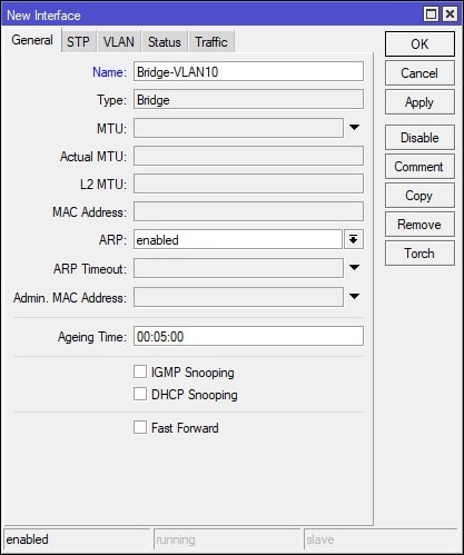
In Winbox, select Bridge on the left-hand side and navigate to the Bridge tab. Click the + (plus) button to create a new Bridge. Set the bridge Name to “Bridge-VLAN10”. See screenshot for details:
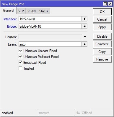
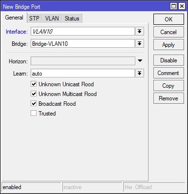
Afterwards, navigate to the Ports tab and click the + (plus) button to add an interface to a bridge. This step will need to be done twice, once for each interface that is added to Bridge-VLAN10. Add interface “Wifi-Guest” and “VLAN10” to the “Bridge-VLAN10” bridge. See screenshots for further details:
Assign a Subnet to the New Bridge
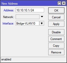
In Winbox, select IP on the left-hand side and navigate to Addresses. Click the + (plus) button to create a Address/Interface assignment. Set Address to “10.10.10.1/24” and Interface to “Bridge-VLAN10”. See screenshot for details:
Create a DHCP Server
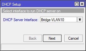
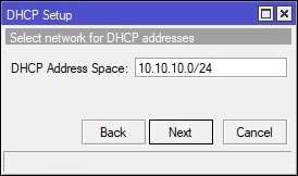
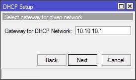
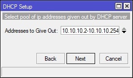
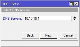
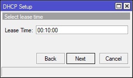
In Winbox, select IP on the left-hand side and navigate to DHCP Server. Under the DHCP tab, click the “DHCP Setup” button and finish the wizard to create the DHCP server for the guest WiFi. See screenshot for details:
Create and Place the Firewall Filter Rules
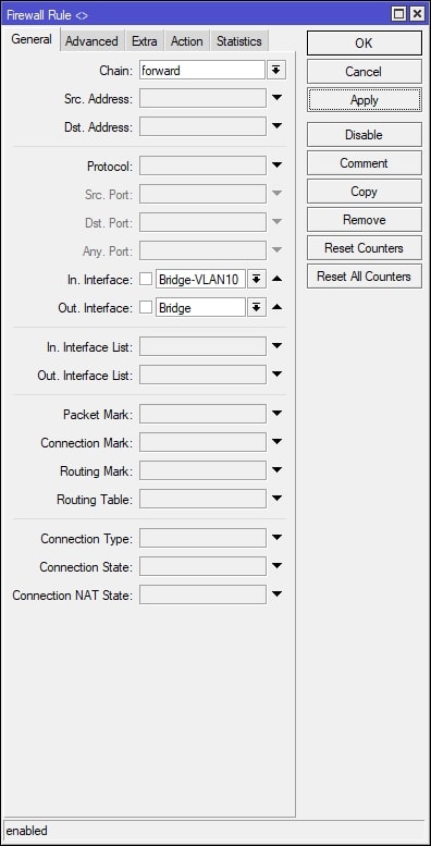
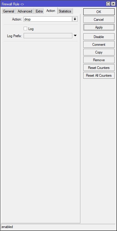
In Winbox, select IP on the left-hand side and navigate to Firewall. Under the Filter Rules tab, click the + (plus) button to create a new filter rule. See screenshot below, which shows how to create a firewall filter rule to block guest VLAN traffic to the private network ONLY. After creating the new firewall filter rule, place the firewall filter rule accordingly in the firewall filters list – order matters. It is your IT department/provider’s responsibility to test the security between between the two separate networks to ensure that the guest network on VLAN10 (Bridge-VLAN10 interface) cannot communicate with devices/clients on the private network.
If needed, a second rule can be added to block traffic from the private network to the guest VLAN network. In order to do this, simply create another rule, but swap the values for the “In. Interface” and “Out. Interface”. It is up to your IT department/provider’s security policies on how to implement the firewall filter rule. This example uses the network interfaces that were create on the MikroTik to separate the two networks, but it can just as easily be done IP address with slash notation (CIDR notation) if need be. Again, it is up to your IT department/provider.
This entire guide has been GUI based, but I’ve decided to include the following commands below, which will create both firewall filter rules to block traffic from guest to private and from private to guest. The entire command can be pasted in the MirktoTik terminal. Keep in mind that after the filter rules are created that they still need to be placed accordingly within the firewall filter rules list.
Thanks for this – it works a treat. I’m new to RouterOS and to be honest, complex routers – I’ve configured firewalls but the routing was already all in place. I understand the principles and I get the general gist of what the above is doing. Just need to go back and do it again, understanding each step along the way! To be honest, it’s mainly the VLAN stuff that I need to know more about.
You’d need to create firewall rules that allow both networks (guest and private) to communicate with one another, or at the very least allow specific IP’s to speak with one another. Depending on the ammount of files/sizes, it might be preferable to transfer the data via third party service such as Dropbox as I don’t recommend opening the guest network up to any network, but I understand circumstances may differ. In this post, the following firewall filters block traffic between the guest and private networks:
Thanks, this works great, except for one thing: the DHCP server for the guest wifi is not working for me. I’m doing something wrong, but I haven’t figured out what yet. Any ideas how I can track down what I’m doing wrong with the guest DHCP server? Thanks.
Well, I tracked it down; you can delete the earlier and this comment.
The problem was that all devices I was testing with had DHCP reservations in the IP space used by the main wifi, so they were offered IP addresses that were invalid on the guest wifi. When I removed the reservations, the guest wifi worked fine.
I’m going to report this to MikroTik: yes, it was my fault (misconfiguration), but the DHCP server could detect this scenario and could ignore the reservation for out-of-scope reservations, and instead give the device an address from the pool. This is what I expected to happen.
Thanks for the guide, its the first blog post that I found that actually made it work for me.
I have two questions:
1. I enabled access to my ppp1-out, and dropped any connectivity from bridge-vlan10 to bridge, so my guest network is now isolated from my other network, and can access only the internet as expected. However, services that I have running in my home network, and are exposed to the internet (DNAT rule in place), I cannot access them. I assumed that If I try to access my home address using its public IP, it will route correctly, but it isnt. Can you explain why it behaves this way? It only works if I setup a filter rule to accept packets from my guest network to my specific node’s IP in my home network.
2. What is the difference between making the guest network in a vlan or just another bridge (no vlan ID), if I already set up a firewall filter rule to drop anything between the two bridges?
Hi!
I did everything according to the guide and I have working DHCP server for guests but guest network does not have Internet access. Main difference: my Mikrotik is not gateway. It’s in LAN working as AP and switch (working flawlessly) but I cannot set it to provide Internet for guest subnet.
Any advice? 🙂

Thanks for sharing your acknowledgment!
This tutorial worked great!
Thank you very much for sharing your knowledge.
It work great.
Can you help me.
I’m stuck on the part that I don’t have network on my guest Network.
Thanks. This got me to understanding how to add an AP.
Thanks for the guide! Worked for me!
Nice guide, just want to add, I just had to add firewall masquerade rule for new subnet , other than that worked for me.
Thanks
Thanks for this – it works a treat. I’m new to RouterOS and to be honest, complex routers – I’ve configured firewalls but the routing was already all in place. I understand the principles and I get the general gist of what the above is doing. Just need to go back and do it again, understanding each step along the way! To be honest, it’s mainly the VLAN stuff that I need to know more about.
Hi. How to allow guest user to access LAN for file sharing purposes? Thank you.
You’d need to create firewall rules that allow both networks (guest and private) to communicate with one another, or at the very least allow specific IP’s to speak with one another. Depending on the ammount of files/sizes, it might be preferable to transfer the data via third party service such as Dropbox as I don’t recommend opening the guest network up to any network, but I understand circumstances may differ. In this post, the following firewall filters block traffic between the guest and private networks:
/ip firewall filter
add action=drop chain=forward disabled=yes in-interface=Bridge out-interface=Bridge-VLAN10
add action=drop chain=forward disabled=yes in-interface=Bridge-VLAN10 out-interface=Bridge
You would instead not setup this rule or preferably change the rule to the following:
/ip firewall filter

add action=accept chain=forward disabled=yes in-interface=Bridge out-interface=Bridge-VLAN10

add action=accept chain=forward disabled=yes in-interface=Bridge-VLAN10 out-interface=Bridge
Thanks, this works great, except for one thing: the DHCP server for the guest wifi is not working for me. I’m doing something wrong, but I haven’t figured out what yet. Any ideas how I can track down what I’m doing wrong with the guest DHCP server? Thanks.
Well, I tracked it down; you can delete the earlier and this comment.
The problem was that all devices I was testing with had DHCP reservations in the IP space used by the main wifi, so they were offered IP addresses that were invalid on the guest wifi. When I removed the reservations, the guest wifi worked fine.
I’m going to report this to MikroTik: yes, it was my fault (misconfiguration), but the DHCP server could detect this scenario and could ignore the reservation for out-of-scope reservations, and instead give the device an address from the pool. This is what I expected to happen.
Thanks for the guide, its the first blog post that I found that actually made it work for me.
I have two questions:
1. I enabled access to my ppp1-out, and dropped any connectivity from bridge-vlan10 to bridge, so my guest network is now isolated from my other network, and can access only the internet as expected. However, services that I have running in my home network, and are exposed to the internet (DNAT rule in place), I cannot access them. I assumed that If I try to access my home address using its public IP, it will route correctly, but it isnt. Can you explain why it behaves this way? It only works if I setup a filter rule to accept packets from my guest network to my specific node’s IP in my home network.
2. What is the difference between making the guest network in a vlan or just another bridge (no vlan ID), if I already set up a firewall filter rule to drop anything between the two bridges?
Thanks it works
Hi!
I did everything according to the guide and I have working DHCP server for guests but guest network does not have Internet access. Main difference: my Mikrotik is not gateway. It’s in LAN working as AP and switch (working flawlessly) but I cannot set it to provide Internet for guest subnet.
Any advice? 🙂